Robot Experiment
Data related to ramp area trajectories are not available or the data are sampled on time scales too large to capture the evolution of individual trajectories. To account for this, we design an inexpensive experiment where the movement of a Boeing 747-400 (Boeing 747) is simulated within the ramp area. In order to capture the spatiotemporal data, we replicate the events using a scaled down robot experiment. The core of the experiment is in using the e-puck robots to obtain data related to real life uncertainties of aircraft trajectories, in particular, uncertainties that are generated from the presence of a Human-in-the-Loop.
The e-puck robot is modeled as a Reeds-Shep vehicle and the aircraft as a tricycle, allowing us to match kinematics between the e-puck and Boeing 747. Once kinematics are matched, experiments are preformed in which human pilots drive an e-puck(simulated Boeing 747) within the ramp area. Data from experiments are captured on video and processed in MATLAB to provide the position and orientation of the aircraft at a given time. The collected data is later used to fit parameters of our stochastic model of aircraft trajectories, enabling us to replicate statistical properties observed in the collected data.

In our experiments we consider a scaled down layout of the Terminal C ramp area at the DFW Airport and the center alley of the CLT airport. The above Figure shows our model of the CLT center alley. By choosing a scale of $4.3$ feet(arena) = $855$ meters(life), the surface of the scaled down ramp area occupies about one half of our 6 ft by 6 ft robotic arena. To scale the taxi velocity of the simulated aircraft it is necessary to know the maximum velocity at which aircraft can taxi on the airport surface. Whereas most operating procedures are well defined by the FAA, aircraft taxi velocities are uncertain with the FAA only stipulating an average taxi speed of at least 17.4 knots be built into the system. Using relevant industry data, however, we can estimate the maximum taxi speed of a Boeing 747 to be 30 knots.
With the maximum taxi speed data we can convert that into an upper bound for the control variables $\bar{v}_L$ and $\bar{v}_R$. Control variables $\bar{v}_L$ and $\bar{v}_R$ correspond to the integer number of step motor displacements per second of the e-puck robot. We first transform the bound on velocity from 30 knots(life) to the e-puck scale providing an upper bound for the e-puck velocity as $v_{max}=.07793$ feet(arena) per second. The e-puck robot is driven by a mechanical step motor where executing 1000 steps per second rotates the e-puck wheel by 1 full rotation in a given second. This defines the following relationship for $\bar{v}_L$ and similarly $\bar{v}_R$. This defines the following relationship for $\bar{v}_L$ and similarly $\bar{v}_R$.
\begin{align*} \bar{v}_L \cdot \Delta \Theta_{step} = \Delta \Theta_L \end{align*}Where $\Delta \Theta_{step}$ is the angular rotation of a single step and $\Delta \Theta_L$ is the total angular rotation of the e-puck wheel in 1 second. If we multiply both sides by the radius of the e-puck wheel, $R_{wheel}$, we obtain \begin{align} \bar{v}_{max} = \frac{ \Delta \Theta_{max} \cdot R_{wheel} }{\Delta \Theta_{step} \cdot R_{wheel}} = \frac{v_{max}}{\Delta \Theta_{step} \cdot R_{wheel}} \label{start_eqn} \end{align}
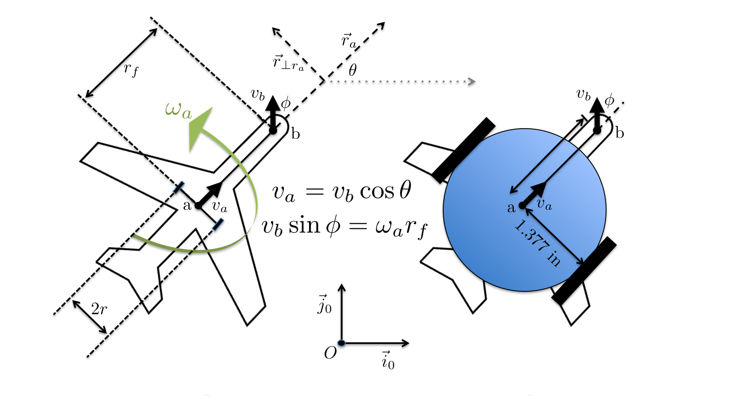
The movement of our Boeing 747 is simulated by the e-puck robot by considering a simplified tricycle model with a main landing gear consisting of two wheels and a single nose gear steering wheel. The motion of a tricycle can be described within the coordinate system $\vec{i}_0$ and $\vec{j}_0$ using points a and b that define the position and orientation of the aircraft and $\phi$ which is the controlled steering angle, see the below Figure.

The velocity at point $b$ is given by separating the linear and angular velocity of point $a$, providing the relationship \begin{equation} v_b \hat{\mathbf{r}}_v = v_a \hat{\mathbf{r}}_a + ( \omega _a r_f ) \hat{\mathbf{r}}_{\bot \hat{\mathbf{r}}_a} \end{equation}
where $\hat{\mathbf{r}}_v$ is the unit vector pointing in the direction of the front wheel located at $b$, $\hat{\mathbf{r}}_a$ is the unit vector pointing in the direction from $a$ to $b$, $\hat{\mathbf{r}}_{\bot \hat{\mathbf{r}}_a}$ is the unit vector that is perpendicular to $\hat{\mathbf{r}}_a$, and $\omega _a$ is the angular velocity around the point $a$. From this, we can derive the two relations \begin{equation} v_a = v_b \cos \phi , \text{ and } \omega _a = \frac{ v_b \sin \phi}{r_f} \end{equation}
During pushback, the velocity of the left and right wheels can be derived as function of the pilots inputs $v_b$ and $\phi$ as \begin{align} v_L = v_b \cos \phi \Big(1 - \frac{r}{r_f} \tan \phi \Big), \,\,\, v_R = v_b \cos \phi \Big( 1 + \frac{r}{r_f} \tan \phi \Big) \label{push_control} \end{align}
During taxi, the velocity of the left and right wheels can be derived as function of the pilots inputs $v_a$ and $\phi$ as \begin{equation} v_L = v_a \Big(1 - \frac{r}{r_f} \tan \phi \Big), \,\,\, v_R = v_a \Big( 1 + \frac{r}{r_f} \tan \phi \Big) \end{equation}
This mapping provides the match between the aircraft and e-puck kinematics, i.e., given the pilots input $v_b$($v_a$) and $\phi$, we can compute the e-puck's control variables $\bar{v}_L$ and $\bar{v}_R$ so that the e-puck pushes back (taxis) analogous to the aircraft.